Sunday, December 8, 2013

Why, How and Where to move to a Native Ethernet Back-haul?

" Transport evolution from one technology that is being phased out to another technology is a scientific thought process and is not governed by a raw abhorrence of the technology that is phasing out"

                                                 ------ A recent conversation output

My dear friends of the transmission fraternity, 

SDH (Synchronous Digital Hierarchy), a technology that actually governed the transport networks of the operators for more than 3 decades is slowly but steadily phasing out. This is plainly due to the fact that the services are moving more towards a packetized format than being a TDM oriented service.

I NEED ADVANCED FEATURES:(Wrong Reason)

However, if this statement is true, one thing is also true that Ethernet is very well able to ride over the SDH as EoSDH with or without MPLS capabilities making use of the existing back-haul infrastructure. The variant gives all the facilities of a packet switched network in its full context, meaning that you can have BW sharing, instancing, QoS but the only issue is that the media is SDH based. However if you are going to a more native variant of ethernet then also all the facilities of the MPLS and Ethernet if available over a more native architecture.

So if the decision of going from TDM back-haul to a more Native Ethernet back-haul is actually for the quest of more advanced features like BW sharing, QOS, Instancing  then the reason for movement is wrong and not justified. Probably the guys of planning could not actually plan the network well and could not exploit the features of next generation in the existing network, so they are doing nothing but adding more over-heads to the network expense. Probably the management is also not concerned because they might be having he money and the shine of new back-haul is actually curtaining the logic to a large extent.


THERE ARE OVERHEADS IN EOSDH: (Wrong Reason)

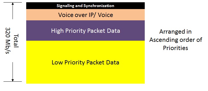
One of the main reason other than the advanced features to move to a more native Ethernet back-haul may be that EoSDH in the essence of it contains a lot of overheads that may be required to be added in order to make the GFP encapsulation, thus affecting the throughput. The real equation of throughput is explained in the figure below.

As we can see in the figure that of the total overheads that are added in the EOS architecture the contribution of EOSDH GFP with GFP FCS is only 12 Bytes.  (* in the picture are the bytes that are added irrespective of the fact that your are going on Native Ethernet or on EOSDH).

The GFP FCS is an optional requirement so it means that the compulsive contribution of the EOSDH in totality is only 8 bytes.

Now the question is does this actually affect the throughput of your system? The answer is no.

This is because of a common science. When Ethernet packet or a stream of Ethernet frames actually traverse through the line then there is an object called as the IFG. IFG is the inter-frame Gap that may be continuous or it may come after a burst of frames. Generally this IFG is of 12 Bytes where these extra overheads are actually accomodated. So the fact is that if this is a shaped continuous traffic then movement through the EOSDH will actually not make any difference to the throughput as the overheads are actually packed in the IFG.

So the overheads of the EOSDH actually do not make any sort of difference to the throughput of the entire Ethernet line. Also if this would have been then so many point to point ILLs would not be running on leased networks of service providers who conventionally carried them on the EoSDH part only.

SO WHAT MANDATES AN ETHERNET NATIVE BACK-HAUL

Ethernet Native back-haul is mandated by the following functions.

1. Rise in the Ethernet BW requirement Vis a Vis a common TDM BW requirement.
2. Last mile devices like BTS, Node B moving from a TDM handoff to a more Ethernet handoff.
3. Requirement of reduction of Form Factor.

All these three points can actually be addressed simultaneously by looking at the structure of a device that is carrying the Ethernet over SDH.

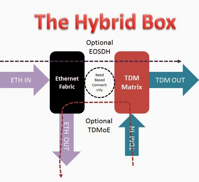
The device that is carrying the Ethernet over SDH is actually utilizing dual capacity of the box. It is using a part of the Ethernet Fabric and it is also utilizing the TDM Matrix capacity of the same box. This means that if the requirement is actually 1Gb/s of BW utilization then the actual reservation that is done in the box is 1Gbps of the Ethernet Fabric and 1Gb/s from the SDH matrix. The figure below explains the same.


So as we can see in the figure that the capacity is used in both the ETH and the TDM matrix. This leads to dual overheads on the box and as and when there is an increase in the BW there will be more and more requirement to increase both the ETH fabric and the TDM matrix.

So typically in the aggregation and in the core regions of transport where the quantity of Bandwidth is typically high there the proposition of carrying it on a EOSDH may prove to be more expensive as the rise of Ethernet BW also results to a rise in the requirement of TDM matrix, which can be avoided by going native.

The dual increase of two fabrics actually also mandate a rise in the form factor and power usage, which is an unnecessary loading on the OPEX that is not justified.

Also as the last mile devices move more and more to giving out the Ethernet output then there will be more and more requirement of actually taking them natively as this will result in less consumption of the form factor of the box and less consumption of power.

Now I need not be worried on my TDM matrix to carry my ETH traffic in the device as this device is optimized to carry it natively as well.

SO HOW DO WE ACTUALLY DEDUCE THE BOX?

A box that is carrying Ethernet as ethernet with all the advanced features and also has a capability to carry the native TDM in its native form with a TDM matrix limited to the quantity of that is required is actually the type that we can be looking for. Of course there should be also a facility to take EoSDH and TDMoE as and when required.

As shown in the figure most of the ETH traffic is carried natively and so is the TDM traffic. There are need based connectivity for optional EoSDH and TDMoE. So this box actually provides the full spectrum of transmission and give the best out of the two worlds.

Needless to say that when there is a kind of division across both the domains of Ethernet and of TDM then there is also a reduction in the form factor as now each and every matrix can be weighed in the individual context and ones dependency on other is very less.

NOW THIS ANSWERS THE  WHY AND HOW ; FOR THE WHERE READ ON:

It is not necessary to go native everywhere as this may lead to a kind of a demand for fiber cables everywhere. So one major thing that determines where actually to go for this kind of boxes is very crucial.

The operator must look for the BANDWIDTH USAGE / UTILIZATION as explained already in a previous blog article.

Utilization Based Provisioning

So the decision to go native or not actually depends on how much this utilization can be optimized on. Actually if we see clearly then the concentration of BW is more towards the aggregate and the core so it is much suitable to go native on the core and the aggregate so as to conduct an Ethernet Off-Load.  The access where there can be a considerable over-provisioning can actually continue to be in the EoSDH flavor until it tends to choke the matrix.

Actually by doing this following things are happening which is more good for the network.

1. OFF LOAD IN THE CORE.
2. UTILIZATION OF THE SAME DEVICES.
3. NOT MUCH LOAD ON THE CAPEX.
4. SERVICE CONTINUITY.
5. PAY AS YOU GROW.

Hence a more intelligent decision would be to follow the scientific norms of transmission planning and to actually deduce the introduction of Native architecture in places where it is required.

This will allow gradual packetization without affecting your pocket.

Remember.....

While the company sales guys are actually responsible for the TOPLINE it is the network PLANNING that contributes the most for the realization of a good BOTTOMLINE. 

Till then all of you take care and Follow Science not Trend.

Cheers,

Kalyan

My E-mail incase you want to mail me

Thursday, December 5, 2013

Provider Bridge and Provider Edge

"The essence of planning a packet network is to understand the flow of traffic first, not only from a level of 40,000 ft but also on ground......."

                                                                                               After meeting various people

My Dear Friends of Transmission Fraternity, 

Packet network planning is all about knowing the flow of traffic and the entire in and out of traffic while the transport is being planned. When we talk about a packet network we usually talk in the terms of L2/ MPLS/ L3. The L3 is not actually a transport solution but more of a terminal solution to the traffic, so we can consider the L2 and the MPLS to be a kind of a technology that actually helps in efficient transport of the traffic.

Two basic terminologies come into the being in realizing such transport systems.

1. Provider Bridge.
2. Provider Edge.

While these are the two major technologies that are actually involved in the realization of the packet network we need to first understand one word very clearly "PROVIDER"

So who or what is called as a provider?

A provider entity is any system that helps in interchange and exchange of any traffic that may be Unicast, Broadcast or Multicast.
This is a simple example and definition of  a provider. So this means that any network that is shipping the traffic content from one point to another point with or without intelligence may be referred to as a provider. A provider can be a telco or it can be any network entity in the system that transports traffic.

This provider can act as a Bridge or as an Edge. The term Bridge and Edge is actually used in the context be the way the traffic is flowing through the network elements and the location or the point at which the MAC address is learnt.

L2 PROVIDER BRIDGE NETWORK:

A L2 Provider Bridge Network is actually realized by connecting various L2 switches together in the network. As known the L2 switches work on the principle of Mac learning and forward packets through the ports in the manner the source mac addresses are learnt. Every L2 switch entity is thus a Mac learning entity in the system.

So if a L2 provider bridge network is selected then at each and every point actually the traffic is forwarded after the Mac address is learnt.

Let us see the following example in the picture.


The figure actually shows how the traffic flow happens in a provider bridge. As we can see that at every transit point the traffic is actually bridged. Bridging means reforwarding of traffic by means of learning mac addresses. So if a traffic has to enter Node 1 and go out of Node-4 to a particular destination mac address, the destination device address should be learnt in all the NEs in the entire network so that the traffic can be bridged.

Each and every flow instance is called as a bridge and since the traffic is always having to pass through these bridges as they transgress the Network elements these are called as Provider Bridge elements.

Limitations of a Provider Bridge network:


  1. Mac address to be known at every point so there cannot be any kind of full point to point services in the network that is not requiring to learn mac. 
  2. As and when the customers are increasing in one of the endpoints the vFIB capacity of all the network elements are to be upgraded. 
  3. The whole system and all the NEs in the network are to be upgraded in configuration as and when the number of users are increasing. 
  4. When there are more number of NEs introduced in the transit there will be a considerable addition to the delay latency time that it takes for the traffic to flow. 
PROVIDER EDGE NETWORK:

A provider edge network tends to eliminate all the limitation aspects that are actually found in the Provider Bridge network. The Provider Edge network actually works on the principle of tunneling of traffic from one point to another point. So if a packet is to be sent from say Node-1 to Node-4 there is a tunnel that is created from Node-1 to Node-4 and on this the packet is actually put on. 

The below picture will clear this:


As shown in the picture this is actually a mechanism where the traffic is tunneled across the intermediate node so that the intermediate nodes do not need to know at all about the Mac Addresses.

This principle makes the network more scalable and more agnostic to mac learning. The mac learning concept is used if and only if there are multiple endpoints in a service. The intermediate points are not a part of the service integration but only points where the traffic is made in and out. 

Since the tunnel is a point to point entity there needs to be actually no realization of MAC in the system and the traffic is sent end to end. 

This can be done without the learning of the MAC. What actually happens in the transit point is that the traffic enters with a "Label" and goes out with another LABEL. 

that is the reason why the tunnel is also called as an LSP (Label Switched Path). 

The Label Switched path can have its own protection as we discussed in the MPLS section also. 

So what should be remembered by my friends of the Tx Fraternity:

1. Discuss and realize how you want to scale up the network. 
2. Understand and think which design is suitable PB or PE. It is not that PB should always be rejected. In smaller networks PE can be a major overkill. 
3. Know the service, whether it needs mac learning or not. Unnecessary bridging can kill processes in the card. 


Every process in telecom transmission is a function of "Science" and not a result of "Trend". Remember you can be a lamb and follow the trend like following the herd, or you can be scientific and make your network so well that it actually sets the Trend. 

In the war between Science and Trend.... Science has and will always win. 

Till then, 

Cheers, 

Kalyan

Saturday, September 14, 2013

Efficient BW Planning and Provisioning in Data Networks

THE MAIN ISSUE FROM TRANSFORMING FROM A CLASSICAL TDM NETWORK TO A MORE COMPREHENSIVE NEXT GENERATION NETWORK THAT HAS A HOMOGENEOUS MIXTURE OF TDM, PACKET AND OPTICS IS THE INABILITY TO MODIFY AND MOULD ONE'S PERCEPTION....

From my recent experiences (Some bad... Some good...Some "horrible")


My dear friends of the Transmission Fraternity, 


Good Day to all of you and wish you a very happy weekend ahead. In India, this is the time of Ganesh Puja and like any other colorful festival this is of a very high importance to the social and religious fabric of India. But... wait a minute...... how does Lord Ganesha figure out in our field of Telecom???? Confused? Well not so. 

Today let us understand the logic of celebrating Ganesh Festival and its significance to Telecom. Planning and provisioning in Telecommunications is much about taking the right decision in the most economical manner to optimize the network, so that the delivery and then the sale of the service is more and more on the profitable side of the business than just an obligation of delivering it. This is just like how Lord Ganesha, by his intelligent ways of solving problem salvages any situation without resulting to much of overheads and conflicts. 

A person who is actually designing the network in such an aspect so that it can generate long term revenue without investment of much of physical resource, should be a planner, a more scientific one, however one who is only doing it for the heck of delivering the service, is more of an implementer or simply a "Copy & Paste" person. If the network is not bringing profitable revenue, then for sure the planning of network has been wrong. More quickly it brings profitable revenue, more efficient has been the planning. Just like Lord Ganeshas ways, a planning engineer should be the revenue optimizer and reliever of technical pains that an organization may foresee to deliver a service. 

Let us take an example for understanding this:


There is a network of Wi-Fi and Mobility where there are  5 access nodes in the access rings with one NodeB each and one Wi-Fi access point each. The peak BW of a Node B is say 28Mb/s and that of the Wi-Fi is around 44 Mb/s.  There needs to be an access network planned for the aggregation of this 5 nodes.  How to do it?

There may be several ways of implementing this aspect and there may be several ways to deliver the services.  Let us see the conventional (less profitable) and the non -conventional (More - profitable) way of delivering this. 

CONVENTIONAL WAY:

The conventional way is the pure transmission way where every BW is important, whether it is being used or not. 

So the following calculation is used. 

5 Node Bs of 28 Mb/s = 5x28 = 140Mb/s 
5 APN of 44 Mb/s = 5x44 = 220 Mb/s 

Total = 140 + 220 Mb/s = 360 Mb/s

Conventional Planner of a good nature :

On a SDH back-haul network this would be taken to be a full 360 Mb/s of Provisioning which would mean a full ring of 360 Mb/s = 8XVC-3s or even 3XVC-4s.  Hence a ring of 8XVC-3 is established in the entire system of EoSDH with or without MPLS and then the following logical network is realized. 


As seen in this picture each and every access node has a drop one of Wi-Fi and one of the NodeB. The total Bandwidth expended in the ring is actually 400Mb/s or 8XVC-3. This is more than the sum of the entire peak Bw of all the sites. 

So the planner here is assuming the following and this is the mistake. 

> In this access ring there will be always peak traffic from all the NodeBs and all the Wireless APNs all the time. 
> There will not be any kind of treatment of traffic to which should be high priority and which should be low priority. 
> Both the services should get the dedicated BW, whether they are using or they are not using in the transport infrastructure.

However, there are some good things that the planner has done which can actually classify him to be a better data planner and having potential. 

> Planner has used less number of WAN ports. 
> Planner has used more instancing and is actually instancing the service in different SVLANs or different instances to avoid any kind of cross talk. 
> There is proper isolation between two Node Bs and two APNs of Wifi in the network. 
> There is proper isolation of Node B and APN in the same access node also. 

I am still assuming that the planner has done this, and if yes, at-least  the basics of data planning is clear to the planner. 

NON CONVENTIONAL WAY:

The non conventional way actually is more data-centric than more transport centric. Let us understand one thing to understand the non conventional way  of planning.  We had BTS and we had the BSC.  So each BTS had around 2 E-1s to 4 E-1s each. This would mean that each BTS is having a capacity to run around 120Voice channels at the same time. With some amount of compression this can accommodate 400 users also simultaneously. So if an area is having more number of subscribers did we increase the carriers. The answer was no. 

A thumb-rule calculation was the fact that for every 1000 subscribers you can actually spend an E-1. This factor was even higher in the case of mobility as there were good amount of compression and a probability of mobile subscriber leaving a site and joining another was very high. 

The only thing was that, this calculation was done by the engineers at the switching centres who are having an idea of the traffic quantum in  a cell site and thus used to give the figures to the transmission. 

This was when you are considering a 2G kind of deployment. However, when the deployment phase goes to more of packet based access (Where the last mile device is Ethernet Handoff) then this flexibility of BW allocation is not to the MSC or the RNC but it is more to the transport. This is because the handoff is now not a fixed multiple of 2Mb/s but a combined port of 100Mb/s or 1Gb/s. 

Not all sites will transmit the peak BW at the same time (Concurrence):

The non-conventional planner actually understands this philosophy of concurrence and  tries to reach to a rational BW in the access ring. The planner uses this concurrence phenomenon to actually reach to a conclusive BW and thus ensures that there is full guarantee of the High available services and there is good amount of availability of low class  services. 

Thus the planner initially does a good amount of ratio and normalizes it to the nearest VC-4 or VC-3. 

In this case the planner sees that the total peak BW of the entire service is 360Mb/s however the amount of traffic will never be of that level. 

Contention and Prioritization (What is important and what is share-able)

Out of this 360Mb/s the signalling and synch traffic (Mandatory and always flowing) accounts to 20Mb/s in the entire ring (2 Mbps per site NodeB or APN).  The rest are good amount of prioritized traffic. 

In the 3G there is a voice per Node B of around 4 Mb/s so that gives another 20Mb/s of committed traffic. 

So 20 + 20 = 40Mb/s of this traffic is totally committed and have to be provided in the line irrespective of anything else. 

The rest 320Mb/s is data and out of which some are priority data and some are non - priority data (Best Effort). 

the figure below explains the entire BW profiling. 


This is the figure that the user is deriving for the entire BW distribution. A high end packet service will contain many streams of data some of which are real time and some of which are non real time. The non real time are the ones that may not be susceptible to congestion as there is re-transmission, only thing that is affected in such cases is the throughput. Hence these services are given the maximum over-subscription. In this figure the Yellow portion is actually attributed to the Non - Real Time data.  Maximum over-subscription is done to this portion only. 

Let us see in the figure below how the BW is attributed and contented in the network. 


So due to this now the BW is provided in the following manner. 

20Mb/s + 20Mb/s + 160*0.5 + 160*0.1
= 20 + 20 + 80 + 16
= 136 Mb/s 
= 1XVC-4 or 3XVC-3

By this process a total saving of Back-haul of 5XVC-3 is done which is equal to 250Mb/s. So the planner is effectively saving 250Mb/s of physical resources and delivering a good service of around 360Mb/s in it. As the number of site increases the user can rationally increase the resources. 

So the final figure is. 


Now in this case when the Voice is of low usage the BW is apportioned to the Packet data. 
There is good prioritization. 
There is of- course good instancing. 

In short... The planner is not only thinking about service delivery but also thinking about Profitable service delivery. Definitely due to low usage of back-haul BW there will be less usage of Physical resources and thus increasing the longevity of the network elements and milking more money from it. 

Such planners like to make the company profitable and want to always have more RPU with less investment. 

ARCHAIC AND OLD SCHOOL PLANNERS:

While we discussed about good planners and very good planners, who try to benefit the network and some of them actually make the network as good profit engines by increasing the longevity, there are some who actually are physical resource guzzlers, and do not have any care of the amount of physical resource usage. They are just planning the network for the heck of service delivery and have no interest in network profitability. They are a pain to the sales personals in the operator industry as they totally reduce the profitability of the network and thus bring no substantial earnings from the service delivery. They are happy just making the traffic through and getting the ping from one side to another. The sales persons of such operators should pray to Lord Ganesha regularly, as each and every order marks in the overall reduction of profitability in the organization. 

Understanding the case above the old school of planning will actually realize the network in the following manner. 

From each access site they would pull two EoSDH trails, one for the NodeB traffic and one for the Wi-Fi APN. 

Resulting into a Logical Topology ( Only the Good planners would understand the word Logical topology though) like this. 


As shown in the figure above let us now calculate the number of VCs that are being used. 

For one Node B 14VC-12 Main and 14 VC-12  for protection Leading to 28XVC-12 each site.So for  5 such node Bs this is 28X5 = 140 VC-12s = 280 Mb/s 

For One Wi-Fi = 1XVC3 for main and 1XVC-3 for protection = 2XVC=3 = 100Mb/s. So for 5 Sites this is 5X 100Mb/s = 500 Mb/s

Total for all provisioning = 780 Mb/s ( WOOOOOW and they still think they will make profit!!!!)

Also let us now look at the number of ports. 

At each access location 2 wan ports are used and in the aggregate 2 for each access this makes 10 WAN ports as opposed to only 2 in the case of Good planning. 

So this means 10 Wan ports and as new access sites are added on the same ring this means more and more WAN ports on the aggregate. 

So in some days the Aggregate module is kept underutilized but the ports are exhausted. 

The planning is done in such a way as if the planner had some kind of an Animosity towards the rising profits of the organization and would like to cut it off by any chance. 


Well this was an example of Efficient .... Very Efficient  and Not at all Efficient way of deploying the same service. 


I leave it upto you my friends as to what you want to become. I would also urge the Sales people in the operator industry to rethink and revisit the technical aspects of their network. 

Telecom service provider is a business where the revenue (Top - Line) is an effort of the Sales people for sure but the Profit ( Bottom - Line) is dependent on how good the planners are in the conception and the implementation phase. 

Remember making more trails doesn't give money, running traffic on it does. 

May Lord Ganesha Bless us all on that note. 

Cheers!!!!

Kalyan

Sunday, September 8, 2013

Viability of MPLS in a traditional network

My Dear Friends of the Transmission Fraternity,

I am sorry, I had to again go on a recluse due to various reasons, some busy schedule and some very urgent professional commitments. But here I am, and I would like to today discuss on one of the burning topics that is taking the Telecom Transmission Industry by storm.

MPLS (Multi Protocol Label Switching)

I know this is a kind of deviation from our regular discussions on the RSTP that I promised but trust me this is important. Why this is important? Well because most of the reasons that are being used to actually use/misuse this technology, especially in India is wrong totally trashy.

So now let us in a very pure mind understand the viability of MPLS in a network that is traditionally a transmission network based on TDM. Can you realize MPLS on it.

If you ask this in the market as an operator, who is trying to enter to the data segment for the first time, you will get very very different answers. Some yes and some no. Some people would tell you that MPLS can never run on a TDM network, some would tell you that yes if the end devices are routing devices and the TDM acts only as the overlay you can realize it.... Well to tell you the truth... These are all vague answers to your pertinent queries. In fact these are not "Honest" answers at all.

To substantiate my point, I would like to draw your attention on this link of Wiki which tells about MPLS. Neutral, short but enough for an operator / beginner to understand to evolve his/her network.

Wikipedia Link describing MPLS

As told correctly in this link MPLS is a Media independant technology, working in between the L2 and the L3 layers of the OSI layer.

So this answers your vital question that MPLS can be actually realized on the boxes that you have purchased to run the TDM network. It can co-exist with a TDM/ATM/FR network that is traditionally old and can also evolve to the new network that are more Ethernet oriented.

The million dollar question is how does this thing happen?????

Well as described in my previous blog posts, if you have read them, there is a concept of EoSDH, which stands for Ethernet over SDH.  An EOSDH trail is a clear infrastructure entity, or a carrier on the layer-1 that encapsulates the Ethernet traffic over the SDH media. This encapsulation happens through the means of GFP (Generic Framing Procedure).  The EoSDH trail or the cross connect acts as a simulation of the ethernet link in the SDH back-haul. Many people, as I said before, mistake this for a SDH trail in totality, however they are wrong as the EOSDH trails have 100% properties of Ethernet and basic properties of SDH inculcated. So this should be treated more like a embedded Ethernet Link than a pure SDH trail.

When you do not have the fibers to make dark fiber Ethernet Link or you have very little requirement of Ethernet Bandwidth, not justifiable to actually spend a dark fiber on the case then EoSDH is a big tool to actually optimize your network.  Here SDH is used as a carrier and not as a service, and the actual service lies on the Ethernet plain.

When this EoSDH trail also has abilities of Label Encapsulation and Traffic engineering then this becomes a trail that can be used to run MPLS on the existing box with existing SDH capabilities.

So how is a MPLS enabled EoS Different from a Normal EoS?

The infrastructure that is created by a normal EOS using only Ethernet is actually a infrastructure that is subjected to the L1 and L2 rules. Under these conditions most of the devices in the Ethernet layer would act as a Provider Bridge. A Provider Bridge is actually an entity that will do the forwarding of the traffic based on Mac Learning or MaC lookup at every point, whether this is the start, end or the transit point.

So in a provider bridge kind of a scenario all the L2 devices have to remember the MAC tables of the entire topology for each and every services. Also as the number of devices increase and the services go high up the number of Mac address entries in the forwarding table would also go High.

This is prevented by making of VPNs (Virtual Private Networks) and VSI (Virtual switching instance) in the network. So VSI is a mechanism that can segregate the services from each other and create a virtual path however, what the VSI alone cannot do is actually giving a dedicated traffic engineered path for each and every sevices across two points in a ring or in  a Network without Mac learning in the Transit nodes.

Below is a picture of how a provider bridge would work with a traffic flowing from point -A to Point-D.  For simplicity I have taken the path of traffic as a liner L2, we will talk about protections later.


As seen in this picture we can see that at every transit location there is a need to learn the MAC address. So the traffic from A to D needs to have vFIB learnings at A, B, C and D. Similarly a traffic from A to C will need to have this in A, B and C.

This method is called the method of  Bridging. At every point the traffic is forwarded or Bridged on the basis of the Source and DA using the MAC table. MAC learning is the essence of learning addresses and forwarding traffic.

Needless to say as the number of transit node will increase so will the number of lookup location and so will be number of learning instances.

A MPLS enabled scenario actually eliminates this. This is shown in the next figure.


 As you can see in this figure there is one more entity in Yellow. This is a logical path that is defined from A to D. This is called as a LSP (Label Switched Path) or more colloquially Tunnel.  Due to this tunnel the traffic which was subjected to a VSI/VPN in A and in D between two ports is not only between one access port and the tunnel.

So the VPN constitutes of on A side the access port in red and the tunnel in yellow and the same is in the D side. This would mean no switching instances in B and C.

So the Mac learning would only be required at the points A and D typically Edges, thus the point A and D are now refered as PE or Provider Edge. While B and C are only going to look at the labels and merely act as transit points without looking at the MAC.

Advantages of this:

Less latency and more scalability. This also ensures more end to end BW integrity, which we will, I hope so see in our next Blog Posts.

This also helps to realize a more point to point architecture in traffic forwarding without the invenstment of physical resources thus saving time and saving money.

What my friends need to remember????

It is not essential to replace the whole install-base that you have purchased with your hard earned money, just becuase you want to include MPLS. Understand the purpose of MPLS before dancing on it.

MPLS is a technology, which is agnostic to device types. The MPLS algorithm and software can be put into any kind of a device be it a L2 switch or a L3 router.

MPLS is a technology that deals with multi-protocol support so if there is a kind of argument on IPv4 and IPv6 be sure this is not MPLS as MPLS doesn't care about which internal protocol is being forwarded.  Many people would flash their papers and give you this dope.

At the end of the day it is the ETHERNET SERVICE  that is actually carrying the traffic, so this needs to be given utmost attention. MPLS is an underlying technology to enhance the delivery of the SERVICE.


Till then .... Have Fun....
 
Cheers,
 
Kalyan

Saturday, April 27, 2013

RSTP/MSTP Part - IV SVLAN Demarcation of services and RSTP MESH topology


Night 02:00 AM
Day: Tuesday

A Call comes suddenly from one person.

" Sir  I had a RSTP ring, I created a new traffic link on the same ring. I did this to ensure another service flow is to be created for a different customer. However just on creating the same link my existing service went down."

Prima facie, when a transport guy hears such a call then it seems very wierd to him. I mean how can a different traffic go down when you just create a seperate link on your topology. For a person who is dealing with transport and for a person who is actually doing transport operations, such a statement is wierd.

However, let us not forget something that Provider Bridge has some different traits from the conventional transport. Not that these are very very out of the world but then as I had discussed in my earlier blog post unlike the TDM where a Trail or a Cross connect is the service Element in the case of Provider Bridge the Trail or Cross connect in the TDM is NOT the service element, it is only the INFRASTRUCTURE. The actual service element is the VPN. So the isolation of services is not done by the means of trail but it is done by the means of SVLAN.

Now let us understand what this guy had done. So we go back to the figure that was there before. A service between A and B that is already created.


There is already a traffic flowing from from Point A to Point B which is located in Client No -2. Now there is one more customer that is taking handoff from Client No 3 and this is a different customer.

So what was the first step done by the guy of the transport.


Now just see what happens when he is doing this.  He feels he will put this new set of  customer on a seperate Link between the root and the client -3 forgetting that the RSTP topology is already converged and the service of customer -1 is already running in this topology. But he decides ignoring all these to create another trail in the topology and this is what happens to the RSTP after he creates the new link.

Now RSTP is bound by its inherent rules, for n number of paths to the root bridge there will be n-1 paths in the blocking state. So in this case the Blocking path is re-calculated. Now you have the Path between Client -1 and Client -2 as blocking and Client-3 and Client 4 as blocking. However the new link that is created from Root to Client -3 is in forwarding mode.

RSTP has done its job but what about the service? The VPNs were actually  built round the ring and are still there. So for the traffic from Point A to Point B, where the VPNs are there they encounter two Blocking paths. This is shown in the figure below.

This is making the whole service go down for Service -1 and that is why my friend called me.

So is this a fault????     NO

Is this a configuration ERROR????? YES

So what should have been the Ideal way to configure the service number -2 in this case, without hampering any traffic?

To this we should again go to the previous posts where the service demarcation is done by the means of SVLAN.


As you can see in this figure you have diffent VPN for different Services in teh same topology and seperated by seperate SVLANs. The SVLAN or the service Vlan actually Seperates the services in a way that there is no Cross talk between different services. Of course they share the same infrastructure.

Each service can be Rate limited to its BW CAP by means of Policy and then both the VPN services can be delivered on teh same infrastructure.  Like this multiple services can be delivered.

This results to a proper ring optimization and good control of the traffic.


But does that mean that you cannot have Multiple topologies in the RSTP configuration?

Is it always that RSTP should always be in the form of a RING?

The answer is NO...

RULE NO 5: YOU CAN SIMULATE MULTIPLE ALTERNATE LINES OF DELIVERY WITH THE RSTP HOWEVER CARE HAS TO BE TAKEN THAT THE SERVICE IS ALSO ACCORDINGLY MAPPED.

So then let us see how the service mapping of Service - 1 between A and B should have been in the topology when another Link is actually present between the Root and the Client -3 considering the same topology convergences that happened before.


If we see at this figure and consider the VPN creations for Service -1 which is between A and B the changes are seen at location Root and Client -3.

In the Root where earlier you had only two WAN ports added you are now adding all the three WAN Ports.

And in Client 3 instead of making a transit VPN with two WAN ports we are not making Transit VPN with 3 WAN ports.

This will result in double failure protection also as now we have two alternate paths as opposed to one, however the most important thing is that the service has to be in accordance.

Same rules and infrastructure applies also for Service from X to Y.

The main thing to remember is that RSTP is an algorithm that is dependant on the topology creation so if RSTP is to be chosen then the Services have to be traced out according to the topology.

It is just like the case that in a linear equation if you have two variables and only one reference equation then you will not be able to solve it. Hence you need to keep one part Variable and one part in reference to it.

In the event you are using RSTP

1. The RSTP algorithm takes care of the topology transitions in the case of failure. ( So this is the variable and varrying part in your network).

2. The service should include all the WAN ports that are part of the RSTP topology. ( This should be the constant part).

In any dynamic algorithm that relies on Topology transitions (OSPF/ERP/IS-IS/BGP) the service is always consisting of the fact that the routing has to have possibilities of all the WAN.

So is the case in RSTP.

My advice to my transmission Fraternity:

1. Once you make the service as per the topology then things are very perfect.
2. Need not create new topologies for new services, because you are actually doing an imbalance to the equation.
3. If you do need to provide alternate paths then make sure that the Ports are also mapped accordingly in the path.

 HAVE A SUPERB WEEKEND AHEAD.........

Cheers....

Kalyan

Coming up next:

How does Switching take place in RSTP 

Thursday, April 25, 2013

RSTP/MSTP Part-III How to create Services in the RSTP Topology

My Dear Friends of the Transmission Fraternity,

The last two posts about RSTP were actually how the functioning of RSTP happens, how there is a convergence happening, Root bridge etc. These properties and configurations of RSTP were actually related to the fact that there is a creation of a RSTP domain. However, what we have not understood in these entire thing is that how are services created in this domain and how is the traffic actually flowing inside the RSTP ring.

Knowing how to create the RSTP ring is just the start of the process. Actually the Data planning requires three major planning aspect and especially in scenarios like RSTP.

1. Topology planning (Covered in Parts I and II)
2. Service Planning and Alternate route Planning ( Is being covered in this section)
3. QoS planning and Service prioritization. ( Will be covered later as we learn about QoS).

RULE No 4: THE CREATION OF SERVICE IN A RSTP NETWORK SHOULD TAKE CARE OF THE ENTIRE RING CONVERGENCE:

Remember one thing over here that RSTP is a property that is closely associated with a topology. So how RSTP will behave is actually decided by the topology and not by the service. The service has to be planned on this ring taking a cue or taking a basis from how the RSTP is actually behaving.

To understand the creation of service let us first take the case of the topology of RSTP that we are taking into consideration for these services.


As you can see in the picture that there is a topology of RSTP , well defined, and we want to send the traffic from Point A to Point - B. We want to send in a way to satisfy the following things.

1. The traffic is able to cater well from A to B.
2. Whenever there is a ring failure in the active section there will be a switch of Path and there will be a proper re-routing of traffic without any kind of loops.
3. At no point of time there should be flooding in the network.

While this kind of traffic is being provisioned there will be the following panic points raised by the people who are actually just shifted from transmission and doing these kinds of configurations.

PANIC No: 1   My traffic is not flowing inspite of the fact "I HAVE CREATED TRAILS and VPN"

Hmm!!!!! let us see what exactly happens in a case like this. The customer, typically a tx guy, calls up and says, I have created "RSTP Trails" and then also traffic is not passing. What do we see exactly in a scenario like this.

The VPNs are created in the following fashion in the L2 modules.
As you can see in this figure that there is VPN created by the VPN has only been created in Point A and Point B. The Client -1 bridge is an intermediate node which doesn't have a VPN at all. The traffic now actually comes from Point A and enters the link between Root and Client -1 and then it enters Client -1. However, since Client -1 has no VPN created the packet actually drops over there.

Hence there is not end to end traffic.

The preconceived notion of the TX engineer is "I have already created the RSTP ring so why should there  be creation of VPNs".... HA HA HA.

Actually the thing that needs to be understood is as follows, while RSTP is taking care of your topology convergence the traffic switching and routing is taken care by VPN. So without VPN routing at every point there cannot be flow of traffic. 

Just like you need Pass Through Cross connects at intermediate points, you also need the VPN Transit at the intermediate switching points.

Now after this rectification is done there is one more problem that is faced by the TX engineer eventually. They come out with the following panic statement.

PANIC NO:2"I have flow of traffic fine, but my traffic is not switching on the removal of a link"

Hmm serious problems raised by the TX NNOC to the TX support and well most of the time this is what happens.

Please see the figure below to understand how the VPNS are created.


No prize for  guessing what the mistake in this configuration is. No doubt about the fact that under no failure scenarios the traffic will flow fine from Point -A to Point - B Via the Client -1 but when there is a failure in the link between the Root bridge and Client -1 then there will be traffic drop.

Most of the Transmission Engineers think that at this time RSTP should take its course.....Well my dear friends, remember what I told before, RSTP is a loop avoidance mechanism and not the protection. RSTP can catalyze a protection response faster but not be the protection itself. Let's see one thing, in a SNCP kind of scenario if you don't provision the other side of the Path then will a Protection take place????? The answer is No... So there is an inevitable requirement to actually make the VPN round through the ring.

First of all let us understand how the problem is occurring in this case with a series of Pictures.


As seen in this figure there is a link failure in the link between Root Bridge to Client -1.


Now over here the blocking link actually comes to forwarding. So as to say that the RSTP convergence has happened.

However, since in the other path there is no VPN created The traffic is actually no reaching the other point through the other path.


So now it is clear that the VPN has to be replicated round the full ring for the proper running of the services. The figure below actually shows how to have services done in the RSTP network.


The figure above is the real way to create the service in the RSTP ring. The Ethernet service is actually routed through both the ways, just like a SNCP Trail which has dual PTPs at drop locations and pass-through at every location, main or alternate.

In such a case the loop avoidance is done by the help of the blocking link. See initially when there is a broadcast the traffic will flow through both sides but the Blocking link will prevent replication and flooding of the traffic.


Some points to remember in the service kinds.
 
1. The service is always a E-LAN instance.
2. There is always MAC learning enabled as the drop points always have to make a decision between two or more paths based on MAC learning of the destination equipment.
3. The intermediate services for just the pass through can be done with Mac learning disabled.


Coming up Next::::

RSTP in MESH.... And service kinds..... 

Monday, April 15, 2013

RSTP / MSTP PART-II Selecting the Optimal Blocking port

Dear Friends of my transmission fraternity,

In the previous blog post I had given the first two rules about how to provision when the RSTP is used as a major loop avoidance mechanism. However, I probably forgot to mention one very important thing in the earlier post.

I said "RSTP is not a protection mechanism it is more for loop avoidance" then how is protection achieved in a Layer 2 circuit?

Answer is a Layer -2 circuit is created when a VPN is formed and a VPN is nothing but a kind of a cross connect that you have in the SDH. However we cannot directly co-relate a VPN with a cross connect because in a cross connect the PTP and the CTP are all hard wired however in a VPN the process is different. There may be two or more than two connectivity points in a VPN and these are bound by something called as a vFIB or Virtual Forwarding Information base. The frame makes a decision on the egress port based on the Mac Table learning and if it is not able to make a decision, well it is flood. So a VPN has two modes, Flooding mode (When addresses are not known) and Forwarding mode (when addresses are known).

So if you already have more than one egress points in a VPN then be sure that the protection is already imbibed, so a VPN would first follow the MAC table and if a path fails then it takes the path that is actually present in the flooding mode. However the basic problem is the point when more than one path is active. Then in flooding state the traffic may be flooded to all the ports and then there may be a condition of loop.

It is to avoid this loop and streamline the protection that RSTP is used.

So when there is a failure the blocking path is unblocked and the traffic is seamlessly switched to the alternate path.

There are also elements like flushing involved in this to actually push the traffic to the alternate path however, this will be covered later.

Rule No: 3  Selecting the optimum blocking path for the RSTP topology

Continuing with the set of rules let us understand that the RSTP also selects the blocking path by the means of

a) Path Cost.
b) Port Priority.
c) Designated Port Number  (Ref Wiki Article on RSTP).

While a novice would actually let the protocol let do this activity and select the blocking port by itself an expert planner would actually exploit this mechanism and influence the selection of the blocking port. Remember one thing while planning of network is done for maximum reliability it also involves an element that when the active and the contingency are both available then there will be more and more stress on the effective utilization of dual bandwidth.

So as to the fact that when the ring is up we can have a dual BW utilization.

Attached is a picture of a mis-planned RSTP ring with respect to path cost and blocking link.


Now what is really wrong in this setup?

First of all the Root Bridge is not planned, which makes all the sanctity of Rule -1 as void. Secondly the traffic is from hub to spokes, and if the right side link is always blocking then in ideal condition there will be a problem in the sense that you will always have 100Mb/s of traffic in the Idle times also. So as to say that when the ring is intact you will only have 100 Mb/s of traffic flowing and no gain in the same ring.

The picture below will explain it.


So as you can see that when the ring is intact the maximum possible BW interchange between the Hub and the spokes are only 100 Mb/s. In a data planning scenario this is like a very novice planning. An efficient planner will not do this, never.

So what is the right way of going ahead? How can we actually ensure that we have a more controlled instance of the RSTP to our benefit.

So friends, let us understand the nuances of creating the blocking link to our benefit. If we see the example above then it is very clear that you have 4 spoke locations in the entire setup and the best possible location of having the blocking link is the link between the second and the third spoke.

To do this we need to understand that which is the factor of  blocking port that is actually in our hands.

1. Designated Bridge Port........ No.
2. Port Priority....... May be but when you have more number of ports in hand it is better not to touch that.
3. Path Cost..... Yes.

The path cost is something that is in our hands and so if we make the path cost of the segment between the second and the third link to be highest then there is most probability that the link would be the blocking link.

Also we keep in mind that the other links' path cost are kept at a much lower side. Because remember the basic statement of RSTP.

"For N number of paths to the root bridge from a bridge N-1 Paths would be in a blocking state"

So the computation of the paths is done taking the sum of all the cost of the segment that is coming from the root to the expected bridge.

Look at the picture below.


The picture explains the following.

> First of all the root bridge is selected as the HUB.  So both the egress ports and all the ports are in actually forwarding state.

> Then the link in-between the second and the third  bridge is assigned the highest path cost. This makes the link as the blocking link.

However, let us understand how optimal is that. For this look at the next picture.


Now as you can see that there is a double usage of the same 100 Mb/s infrastructure. This is happening due to optimally planning the RSTP blocking path. This means that in the ideal scenario where there is no ring cut there will be double the BW available for all the sites. Efficient planning like this will actually lead to more use of EIR ( Extra Information Rate) which can be sold at BE prices.

Thus this kind of planning either saves revenue in a traffic sparse area by conserving resources or generates more revenue in a traffic opulent region by actually investing less resources.


In the next part we will study how to construct services in the RSTP configuration. Lot many parts to go.

Till then some tips.

1. Understand the requirement of BW per pop rather than taking the holistic picture.
2. Compute what will be the total requirement of BW and carefully place the blocking link.
3. Try to divide the RSTP ring in a pattern where efficient division of BW can happen, this is not technology, this is basic mathematics which you and I all have studied and you don't need a crash course for it.
4. Listen to the requirement of customer.... Because if he wants to kill a mosquito do not bring a tank.


And happy planning and provisioning.

Cheers!!!!!

Kalyan...

Saturday, April 13, 2013

RSTP / MSTP how to use them and how they are mis-used. (PART-1)

Dear Friends of my Transmission Fraternity,

First of all I would like to apologize to my transport fraternity for being so late in posting a new topic. Actually these days was very busy and was actually searching for the right topic to actually start this chain of posts.  Many of my friends have now evolved from being a pure TDM guy to a person who has a good hand ont he TDM as well as Ethernet technologies.

However, like every new person the newly evolved people also have a tendency to go overboard and get carried away. Just like babies, who take the first successful step and then get carried away and take further steps which are ostentatious in nature. The result, a fall, a stumble or even worse getting hurt.

My today's topic is dealing with one such stumbles that newly evolved people have. But before I start please note one thing and one thing very seriously. Technology is something that always changes and evolves, so carrying a baggage of so called "Experience" in your head would actually not help. Learning technology should be understood with the fact that every day you are a fresher.

The word "Experience" is good to understand what were your mistakes in past and what "Should NOT be done" however what SHOULD be done is governed by serious rules of technical understanding and YOUR and only YOUR SKILL........

Today we are going to talk about RSTP/MSTP in the network of Layer-2. Understand that RSTP/MSTP should be only used when you are having a Layer-2 emulation. When the Ethernet is only needed to be encapsulated in SDH and sent from one point to another then the Layer-2 should not be mixed with it.

As I have mentioned in the previous blog the EoS trail is just an infrastructure and not an entity that decides the flow of the traffic. The actual decision of traffic flow is taken by the VPN or the EVC.

Misconceptions about RSTP:

1. RSTP is a protection mechanism in Layer-2.
2. RSTP should alwaysbe used in L2 implementations.

 Facts:

1. RSTP is a loop avoidance mechanism when Ethernet rings are formed.
2. RSTP is not mandatory, it should be used and judiciously enough for L2 simulations. Better off to be used when the number of NEs are less.


While I am not explaining what is RSTP  because you can really find this in the link below.

RSTP Explained properly in Wikipedia

We should be clearly understanding when to use RSTP and most important when not to enable RSTP.

RULE -1: USE RSTP ONLY IN SMALLER DOMAINS

The rule is very simple. Remember RSTP is a data plane protocol and has a lot of exchanges of BPDUs from one to another. So unnecessary loading of more and more elements in the RSTP domain may create and is infact creating problems in many networks. The best example is to create smaller domains of RSTP.

In the case these domains need to be interconnected wth each other this should be done in two ways.

1. By means of Trunk trails where RSTP is disabled.
2. By means of Layer -3 segmentation.


As you can see in the picture that various domains or rings of RSTP are actually segregated by interconnections of RSTP disabled links. If the traffic was to travel from a NE in ring -1 to a NE in Ring 2 then it actually would have the RSTP loop Prevention in the ring and then would travel the gateway links.

The gateway links can be protected by means of Layer-1 protection or ASTN. If these links are that between two routing elements then they are actually running the OSPF or a simple CIDR alternate routes.

What happens if you enable the RSTP on these links?????

Well, a mistake that all my tranmission friends do, and yes pay heavily for it and also ring the guts out of the support centres.

Understand that RSTP is a topology based protocol. If this is enabled  throughout then you will not have multiple domains of RSTP but a single converged domain of RSTP. Hence there would be only one root bridge in this entire setup. And this may be any one. The BPDU flow path is now much more complex than simple ring paths and this makes making flows and VPNs more difficult and trouble shooting even more difficult.

This also results into more overloading of the CPU of the NEs which result to NEs being stuck and NEs being mis managed and traffic going hay wires. In short....Total .... Sheer....MESS......
Of course, this also lets your boss and your management think; "TDM waalon ko ye manage karna aayega ya nahin"....

So my transmission fraternity, please do not do this mistake and understand the intricacies.


RULE NO: 2 SELECT A PROPER ROOT BRIDGE

If you read very carefully the document of RSTP then you will understand that it is the selection of Root Bridge that happens first. Letting a protocol actually select the root bridge is the work of a nerd fresh pass out, who lets the system actually control him. A clever planner and a true transport "ENGINEER" and not a "FREAKING ONE MONTH COURSEWARE" will actually call his own shots and plan the root bridge in the right manner.

So interpret the document carefully of the protocol. The purpose of the Root Bridge is actually to guide the entire process of the network. So the root bridge should always preferably be the aggregation point of the Network. Most of the transmission networks are of Aggregate and collector/access kinds so in this it is very easy to locate as to which is an aggregator and which is an access.

The true engineer would actually lower the bridge priority of the aggregation node an then would keep the priorities of the other access nodes at par. Also he would keep the bridge priority of the alternate node that would become bridge at the second lowest figure so that if the root bridge fails that NE and only that NE becomes the alternate root bridge.

This system gives him good control over the network and then it also enables him to have better trouble shooting and more towards a self healing network.

I am putting two pictures over here. One of this is Right way and one of this is the wrong way. Let us see the wrong way first.


The next picture is the right way of configuring the RSTP ring. Which truly a transport engineer does.

What happens if you do not follow this rule????

Hmm, there can be many excuse not following this rule. eg

1. Why should I not stick to default? Well, default password for windows is also no password and even that is asked to change.

2. My guidelines from planning says not to change default values??? I wished your guidelines also repaired your faults when they occured and trouble shot themselves. But unfortunately they don't do that.

3. I will have to maintain a table?  If you are sensible enough you will know for sure what is the aggregation node. So you won't need to maintain a table.

The bottom line is that when you yourself give the bridge priorities then the root bridge and alternates are sure shot ones. So even if there are any replacements in the rings then these replacements do not change the overall computation of the RSTP.

This means that we will actually have more control all the time, even when such replacements, removals and addition activities are done in the network. You don't need to worry about your RSTP going for New Bridge selections again and again.

Another thing is that it helps you optimize traffic. Which we will discuss in the next part.


I will post many such articles on the deadly RSTP and MSTP.... Till then my transport friends please remember the following.

1. Do not play with parameters in Data, as each and every one of them have their significance.
2. Before doing deployments keeping only default in mind just understand the technology.


Still to come in the next parts.

1. Blocking port selection.
2. Traffic optimization.
3. Flow routing in RSTP.

Have a great week ahead.

Cheers!!!!!

Kalyan.