The
piece of article that I am writing today is actually influenced by one of the
questions that was raised by Javin Shah. Javin had asked me on facebook a very
interesting question pertaining to the
last blog-post.
“
In the recommended configuration of using only one EoS across two different
elements for different services, what would happen if there is a problem or
looping in one of the services? Would it also not loop my other service? In
such a case why should I not go with the separate EoS trail approach?”
This
is one of the major worries due to which a transmission engineer actually
prefers to do separate EoS trails for separate services and not consolidate
them in one NNI. This is the point where the user is actually considering the
EoS to be actually a service and not an infrastructure.
When
I say the word “Infrastructure” let us first understand what is infrastructure
in the terms of telecom transmission provisioning.
Infrastructure
is actually an entity on which (and this preposition is very important) the
actual service runs. So if the service is a VC-12 trail the infrastructure for
the VC-12 trail is the Channelized VC-4 and the infrastructure for the
Channelized VC-4 is the Optical Fiber link.
Please
see the figure below for a ready reference.
As
we can see in the Figure it is seen that the actual service (entity carrying
the traffic) is the VC-12 Service trail from one point to another point.
However this service is actually based on the Channelized STM-1 on which it
rides or the Terminated VC-4 and the Terminated VC-4 is based on the Optical
Fiber link maybe of STM-1/4/16 or 64.
A
thing to note over here is that :
One
Optical Fiber link may contain many Channelized STM-1s
One
Channelized STM-1 may contain many VC-12 Services.
So
the Optical fiber is the first layer of infrastructure and the Channelized
STM-1 is the second layer of infrastructure.
Now
if a user desires to may two trails of VC-12 service it is not required to
actually have another set of Optical Fiber or another set of Channelized
STM-1. This means that the
infrastructure is common for two trails of VC-12. However the traffic of one
trail of VC-12 does not inter-mix with another trail of VC-12 and also the
service ill-effects are also not carried over. Each VC-12 trail behaves as an
individual service.
So
as to say the service in the case of both the trails are segregated and do not
interfere with each other, whether positively or negatively.
Same
actually applies for the case of Ethernet services on EoS. However here the
definitions slightly change as the layer of service is shifted one Layer up.
Remember, we are doing this on Layer-2. In the case of our Layer -2 services or
VPN the following picture actually shows the mapping of the infrastructure and
the Service.
K-L-M
IN SDH IS SAME AS VLAN IN ETHERNET (FOR OPERATIONAL PURPOSES):
In
SDH/TDM services the K-L-M indicator is the service differentiator similarly in
the case of Ethernet services the service De-limiter is actually the VLAN. Just
as in SDH as for a new K-L-M a new service trail is built in the case of
Ethernet we have a different VPN for a different VLAN.
Hence,
the VLAN actually forms the basis of the demarcation of the service.
HOW
IS VLAN DIFFERENT FROM THE K-L-M:
Having
understood the concept of VLAN as a service is actually different from K-L-M.
The Vlan a tag that is put on the data payload so that it can be identified and
carried in the Packet Network through a VPN transparently without any kind of
interference. The link below provides a conceptual property of the VLAN.
In
the case of VLAN there are priorities also so that we can have multiple streams
in one Vlan with separate properties. The prioritization is something that is
apart from SDH that happens on the Ethernet networks (Will be explained later).
A
K-L-M is a logical indicator in the physical layer wheras the VLAN is a
instance separation of different streams.
However,
for operational constraints just like in a fiber we can map different services
to different K-L-Ms the same we can actually do for the Ethernet services,
mapping to different Vlans, in the EoS infrastructure.
WHAT
IS TO BE UNDERSTOOD FURTHER:
Just
like we do not have any cross-talk between the K-L-Ms of two different trails
on the same Fiber link same way two different VLANs do not share information
with each other even if they are on the same EoS trail.
Hence,
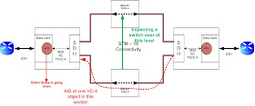
when one service is affected or looped it is only that service which will face
a problem and not the other service as the VPN/VLAN is different.
This
is explained in the figure below.
SO
WHAT SHOULD MY TRANSPORT FRATERNITY REMEMBER:
1.
The
service layer is to be identified for each and every service. A new service in Ethernet
is not a new trail, the trail can be the same however the service is identified
by VPN. This is the basic reason why the end user doesn’t mention port number
of K-L-M in such cases. They mention VLAN.
2.
Data
of one Service never interferes with the data of another service.
3.
If
there is a malfunction/looping/broadcast in one of the segments of the service
then the other service is never impacted.
4.
The
user should remember that the Vlan can be reused just like the K-L-M can be
reused in a different segment.
SO
MY FRIENDS, REMOVE YOUR APPREHENSIONS AND GET OUT OF THE TYPICAL TRAIL
PROVISIONING CUCOON AND IDENTIFY WHAT TO PROVISION WHEN…………


